updated from: https://www.dougrice.co.uk/cgi-bin/wiki.pl?WebAudio_Rev62
I had recorded the signal between a BT Textphone and the telephone network using Audacity. It provides these spectrogram. I have added the labels, to understand and confirm the features seen. I needed to decode the blobs to confirm what they were. This page records this adventure.

and

My knowledge is like a JigSaw? - lots of pieces that need to be put together. Some annotation was possible from the ITU V.18 spec.
To help annotate the spectrograms, some decoding of the samples was done with this "proof of concept" webpage, that I mashed together, and run from my desktop.
This webpage http://www.dougrice.plus.com/dev/UART/UART2_20230423_ProofOfConcept.htm is an early Proof of concept from 23/04/2023 to see if I could decode the bits Audacity could not decode.
It needed more work to get it to accurately decode the samples. It needs more note to explain what it is doing. It evolved into:
http://www.dougrice.plus.com/dev/UART/UART2_V18.htm
https://www.dougrice.co.uk/webaudio/mic.htm - a mash up / proof of concept to use earbuds to test a Ultratec Supercom Textphone using BAUDOT - Uses WebAudio.
https://www.dougrice.co.uk/webaudio/micBaudotDecodeMerged.html - older version
https://www.dougrice.co.uk/webaudio/m2eCopy.htm - Simple Web Audio example connecting Microphone to earphone. It is useful to explore what happens if you open the page multiple times, and http://ccgi.dougrice.plus.com/cgi-bin/wiki.pl?Integration_And_Feedback discusses mixing signals explores combining signals.
https://www.dougrice.co.uk/webaudio/simpletermModemOne.html - Webpage to drive modem using AT command via USB serial.
It uses JavaScript? and HTML CANVAS to plot debug traces, which were all readily available, using the web browser on my laptop.
The history of text phones is such that ITU V.18 tries to work out how different solutions interwork together. Its like having six different JigSaws? mixed together in the same box!
Modems use V.21 as part of the ITU V.8 protocols and it is unlikely that the USB modem can output these.
However by copying the recorded samples into my webpage, it is possible to decode the ITU V.8 CI messages and TXP sent by some modems.
 ITU V.8 CI signal captured and decoded.
 A  A  A  A  A
 0x41 0xff 0x0 0x41 0xff 0x0 0x41 0xff 0x0 0x41 0xff 0x0 0x41 0xff 0x0
Where the V.21 signal had both carriers, Audacity could be used to filter out one carrier.
I wanted to understand the audio signals used by the BT Textphone's modems plugged into a telephone line. I could record the audio using Audacity, which could display spectrograms. Audacity can export samples. These can be imported into a webpage that could use JavaScript? to decode the modem signals and decode the Text.
 * HTML <CANVAS> and JavaScript? could analyse samples and plot debug waveforms
 * WebApi?-serial can be used to control the modem plugged in using a serial port.
 * Webaudio could be used to play generated samples and possibly capture the microphone.
 * These web tools do not need approval or difficult to purchase software.
 * The wiki and webpages can document this interesting subject that span many decades.
To explore a problem, I can use use webpages, and javascript to experiment and explore. I can make notes in the code or webpage text. This is a scrap book of notes and links.
The webpage is intended mostly for the writer. It could be that the only other readers are random AI tools and chat bots.
It is possible to do Audio in a Webpage.
See: https://developer.mozilla.org/en-US/docs/Web/API/Web_Audio_API
https://ltu.diva-portal.org/smash/get/diva2:1030584/FULLTEXT01 - A very Interesting Document about ITU V.18 Modems that is worth a read.
It is now possible to use a web page to generate and play audio samples and plot graphs using reasonable accessible tools available in a web browser.
https://developer.mozilla.org/en-US/docs/Web/API/BaseAudioContext/createBuffer has an example: https://mdn.github.io/webaudio-examples/audio-buffer/ that plays white noise and I copied and modified to play out modem squarks.
http://www.dougrice.plus.com/dev/UART/example.html generates and plays 12 seconds of white noise to test Android
Web pages now support a large range of WebAPI?, two of which are <CANVAS> for graphics and Audio.
http://www.dougrice.plus.com/dev/UART/xyz.htm tries out some ways to generate sine waves and used the <CANVAS> to plot the samples.
It provides a way to experiment with digital filters.
When debugging DSP that has a stereo DtoA?, it is possible to use one DtoA? channel to provide a debug waveform to annotate the other signal.
I can use JavaScript? to do the maths and plot a graph.
A couple of lines are used as debug.
The state of the UART and sampler can be shown.
It can show when a waveform is sampled.
IIR poles and zeros - explores some ideas about IIR in the feedback.
Other Audio Experiments - Other experiments and links.
This web page started as an experiment and evolved. I wanted to understand the signalling between modems. Audacity is very good. It can record signals and show the spectrum.
The ITU V.18 modem specs for the Textphone have lots of facts to understand. Audacity cannot decode DTMF and modem squarks, so this webpage records my attempts at decoding.
http://ccgi.dougrice.plus.com/cgi-bin/wiki.pl?Modems is an attempt to remember modems.
Textphones is a start of a "virtual collection" of text phones.
WebAudioTextPhones - notes on Textphones
WebAudioNotes - more notes on Textphones, Telephones , RS232
Two-wire telephones summary:-

More diagrams:-
[functional blocks in a phone] has some useful dialgrams for this webpage.
Using a simple wiretap, record the telephone signal.

IMPORTANT: The two LED snub any voltage spikes when you go onhook / offhook. A cheap USB soundcard was used incase the LEDs did not snub and to provide a 3.5mm socket. This is plugged into a laptop running on batteries. We are interested in timing and frequencies.
Export the Audio samples, sampled at mono 8000 samples per second into a text file. Copy and paste them into a textarea on the webpages below.
These pages uses IIR Goetzel resonators / filters to look for the modem's FSK tones that encode the 1's and 0's. These are decoded by an adjustable 300 baud UART to decode text that Audactity cannot decode.
 [samples]--[ notch filter ]--+--[ iir filter ]--[ mark energy  ]--+--[ comparitor ]--[ UART ]--[code]
                              \--[ iir filter ]--[ space energy ]--/
http://www.dougrice.plus.com/dev/UART/UART2_20230423_ProofOfConcept.htm - Early Proof of concept to see if I could decode the bits Audacity could not decode.
NOTE: 2025/04/27 - NOTE: Android UI concern.
In the examples below, to save space, I generate the samples using generateSamples8a() and assign them to the text box you paste into the samples from Audacity.
On Android, the UI chokes when I assign 8000*seconds worth of samples using:-
document.getElementById?( "samples" ).value=generatedSamples
So as a work around, I do not write the generatedSample to the TextArea?.
http://www.dougrice.plus.com/dev/UART/UART2_V21.htm - no longer updated - Try and decode the capture of a V.21 modem and other modems and generate tones.
http://www.dougrice.plus.com/dev/UART/UART2_BAUDOT.htm - This page uses a UART configured for BAUDOT that uses 5 bits and does a crude BAUDOT to ASCII
http://www.dougrice.plus.com/dev/UART/UART2_DTMF.htm can be used to decode DTMF. This uses 8 IIR filters.
and later versions:-
http://www.dougrice.plus.com/dev/UART/UART2_V18.htm - Try and decode the capture of a V.18 modem and other modems and generate tones for different modems used in ITU V.18.
http://www.dougrice.plus.com/dev/UART/UART2_V.18_generators.htm - generate tones for different modems used in ITU V.18.
https://www.dougrice.co.uk/webaudio/mic.htm - a mash up / proof of concept to use earbuds to test a Ultratec Supercom Textphone using BAUDOT - Uses WebAudio.
https://homepages.plus.net/dougrice./dev/UART/micBaudotDecode.html - older version
https://homepages.plus.net/dougrice./dev/DigiSpark/simpleterm/simpletermModemOne.html - Webpage to drive modem using AT command via USB serial.
and copies on another site
https://www.dougrice.co.uk/webaudio/mic.htm - a mash up / proof of concept to use earbuds to test a Ultratec Supercom Textphone using BAUDOT - Uses WebAudio.
https://www.dougrice.co.uk/webaudio/simpletermModemOne.html - Webpage to drive modem using AT command via USB serial.
Audacity was used to capture audio of a modem training up on a telephone line.
https://www.audacityteam.org/ has been useful to analyse audio on phone lines
It has found problems, that a scope would not find. Screen shots provide a useful way to summarise protocols that may take a few seconds to transact.
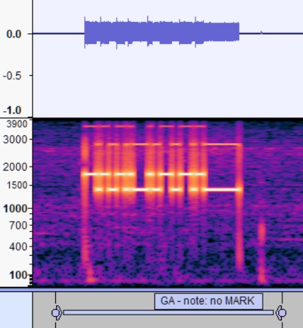
The picture below show Audacity displaying the spectrogram of the capture when a V.21 modem answers an incoming call.
The ringing, 2100Hz ANS, V.21(high) 1650Hz Carrier , V.21(low) 970Hz carrier and burst of data are seen.
Audacity cannot decode DTMF or the Modem FSK signals used by V.21. I cannot work out how to import a WAV file into these webpages and get the samples, but it is possible to export the samples to a text file.
Select all and copy and past the samples into one of the web pages below. They use JavaScript? to analysis it. The CANVAS can be used to plot waveforms and debug waveforms.
Audacity's Analyse spectrum and Spectrograms can establish what frequencies are being used, and sections of interest.
The decoded text can be used to add Labels to annotate the Audacity capture.
Typically the Modem takes a serial signal, using voltages encoding the "1"'s and "0" using MARK and SPACE and uses FSK frequency Shift keying.
[computer: [computer program]--[UART]--]--[RS232 cable]--[ DB25 connector ]--[modem]--[telephone system]--[modem]--[UART]--[computer program]
or:-
[computer program]--[USB modem: --[UART]--[modem]--]--[telephone system]--[modem]--[UART]--[computer program]
These are very useful diagrams from https://docs.rs-online.com/a02c/0900766b800af005.pdf - data sheet for V21 modem.


It is quite simple to analyse the samples exported from Audacity using JavaScript?, using code run for each sample. The pages can be updated as required for the task in hand.
The samples are passed into IIR filters to detect the V.21 FSK signals.
Some logic is needed to decide if the FSK is encoding a "1" or "0".
Logic is used to find the "1"'s MARK and "0"'s SPACE. These are fed into the UART. It looks for the start bit and then clocks 5 bits for BAUDOT or 8 bits for V.21.

Countdown State machines are used for the FSK logic, UART and DEBUG.
The UART emits characters. Parity may need to be stripped, and the decoded text can be displayed.
You can view and study the source code on this early proof of concept page:
http://www.dougrice.plus.com/dev/UART/UART2_20230423_ProofOfConcept.htm - Early Proof of concept to see if I could decode the bits Audacity could not decode.
ITU V.21 used FSK with 1070 +/- 100Hz and 1750 +/-100Hz, or 970,1170, 1650, 1850 Hz. Some modems use bandpass filters.
It is possible to filter out the V.21(high) 1650Hz or V.21(l) 970Hz using Audacity.
This Filter designer: http://jaggedplanet.com/iir/iir-explorer.asp was used to design a Butterworth notch filter
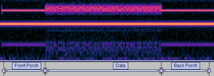
A modem using the ITU V.8 spec, has other interesting bursts of characters to decode as seen in the picture above. Other pages can decode DTMF and BAUDOT captured using Audacity.
Modems use V.21 as part of the ITU V.8 protocols and it is unlikely that the USB modem can output these.
However by copying the recorded samples into my webpage, it is possible to decode the ITU V.8 CI messages and TXP sent by some modems.
 ITU V.8 CI signal captured and decoded.
 A  A  A  A  A
 0x41 0xff 0x0 0x41 0xff 0x0 0x41 0xff 0x0 0x41 0xff 0x0 0x41 0xff 0x0
Where the V.21 signal had both carriers, Audacity could be used to filter out one carrier.
This webpage http://www.dougrice.plus.com/dev/UART/UART2_20230423_ProofOfConcept.htm is an early Proof of concept from 23/04/2023 to see if I could decode the bits Audacity could not decode.
The page uses IIR Goetzel resonators / filters to look for the modem's FSK tones that encode the 1's and 0's. These are decoded by an adjustable 300 baud UART to decode text that Audactity cannot decode.
 [samples]--+--[ iir filter ]--[ mark energy  ]--+--[ comparitor ]--[ UART ]--[code]
            \--[ iir filter ]--[ space energy ]--/
ITU V.18 3.3 says "A CI sequence consists of 10 ONEs followed by 10 synchronization bits and the call function octet."
Table 1/V.8 � Preamble - "Ten ONEs preceding each information sequence , Synchronization for CI sequences 0x00,
The call function octet 0x41 is found in:-
Table 2/V.8 � Information categories
Table 3/V.8 � The call function category
My first pages included the samples in a textarea or between DIV tags but the files got very big to compare using notepad++ compare so I wrote a cscript program to split the files.
https://homepages.plus.net/dougrice/dev/UART/jsUARTsplit.js.txt
My pages now generate test signals to decode to make the download smaller. These can also be played using WebAudio over the sound card , speaker or headset and played into the modem.
V.18 Annex B DTMF is a way of sending text using DTMF characters.
The wire tap used records signals sent and received in mono.
http://www.dougrice.plus.com/dev/UART/UART2_V.18_generators.htm can be used to send signals into the textphone using headphones as an acoustic coupler.
From National Semiconductor Corp, Telecommunications Databook 1987 Edition Application Note 347 , Peter Single and Steve Munich
AN-347 5.8 MM74HC942 and MM74HC943 Design Guide
Squelch Transmitter
 Transmitter squelch is achieved by putting SQT = Vcc
 (SQT is pin 14). The line driver remains active in this state
 (assuming ALB = GND).
 This state is commonly used during the protocol of estab-
 lishing a call. The originate user initiates a phone call with its
 transmitter squelched, and waits for a tone to be received
 before beginning transmission. During the wait time, the mo-
 dem is active to allow tone detection, but no tone may be
 transmitted.
Essentially the Calling modem holds back sending MARK carrier until the called modem sends MARK carrier.
The users need to know if they can send text and should wait until carrier is received from the far end.
Early modems used a hard wired phone to set up the call, and acoustic couplers. In America there was big fight to be able to use a modem with a telephone.
Some calls could be auto answered by a computer awaiting an incoming connections. Auto Answered calls may hang up on loss of carrier.
Later on the dialler was built into the modem and it was plugged into the PSTN line.
The called end could be shared with a phone or another modem.
Hayse modems invented sending AT commands to the modem to control it.
What is going on when you dial using the textphone is not simple.
Some modems send chirps of CT tone ( 1300Hz ) while awaiting ANS 2100Hz tone. See ITU V.25
The BT Textphone in V.18 mode sends CI which uses V.21 to send short bursts of characters see ITU V.18
Some Textphone user use "Voice Carrier Over" - VCO and "Hearing Carrier Over" - HCO ,so interrupt the V.21 carrier during the call.
A user can use VOICE - SPEAK and HEAR, or TEXT - TYPE and READ depending on their need.
The VOICE and V.21 cannot share the same 2-wire phone call at the same time. The user has to use a button to go to VCO and a button to return to TEXT. If the text phone uses BAUDOT, or EDT, the carrier.
If a Textphone has gone to VOICE mode, what does it send when returning to TEXT?
I can use a USB modem to access the RelayUK? service for TYPE and READ. It needs extra configuration to do VCO and HCO
https://homepages.plus.net/dougrice./dev/DigiSpark/simpleterm/simpletermModemOne.html
My USB modem could be configured to disable the hangup on loss of carrier, and you could use the ATD and ATA commands to return to TEXT.
When I used ATD to return to TEXT, it did not send CARRIER so the line remained silent.
If I used ATA it sent carrier and the modem re-trained.
Being able to listen to what is going on and using some of these pages to generate clips of V.21 really helps
ITU V.21 needs ITU V.25 and ITU V.18
My pages can use Web Audio to generate V.21 squarks which enables testing. Getting the a textphone to display text using my generated audio is very rewarding.
Using available resources helped me understand the blobs on the Audacity traces.
The Web Browser is a useful tool!
WebAudioNotes has more notes about Textphones and Telephones
[functional blocks in a phone]
[RS-232 Relatative Signal Timing] RS-232 Relatative Signal Timing
[A UART interfacing to a computer] A UART interfacing to a computer
[Sending AT Commands To A Modem] Sending AT Commands To A Modem
[Telephone Diagrams] Telephone Diagrams
The textphones were different and ITU V.18 lists six modems. From:- https://www.discapnet.es/innovacion/productos-de-apoyo/terminales-de-texto-para-personas-con-discapacidad-auditiva
The most commonly used text terminals for deaf people are:
Not all text phones use and or support all of them. Some support a selection. Some have options not listed in ITU V.18
| Modem | mode | Mark | Space | Baud Rates | V.18 annex | notes |
| BAUDOT | HALF-DUPLEX | 1400Hz | 1800Hz | 50 / 45.45 | annex A - 5-bit operation mode | |
| DTMF | HALF-DUPLEX | N/A | N/A | N/A | annex B - DTMF operation mode | sends letters using * # ending with a digit |
| EDT | HALF-DUPLEX | 980 | 1180 | 110 | annex C - EDT | European Deaf Telephone |
| V.21(orig) | Duplex | 980 | 1180 | 300 | annex F - V.21 text telephone mode | may send CT 1300Hz bursts |
| V.21(ans ) | Duplex | 1650 | 1850 | 300 | annex F - V.21 text telephone mode | ANS sends carrier |
| V.21(orig) | Duplex | 980 | 1180 | 300 | annex G - V.18 text telephone mode | sends CI V.8 |
| V.21(ans ) | Duplex | 1650 | 1850 | 300 | annex G - V.18 text telephone mode | ANS sends carrier |
| Bell 103 (orig) | Duplex | 1270 | 1070 | 300 | annex D - Bell 103 mode | |
| Bell 103 (Answ) | Duplex | 2225 | 2025 | 300 | annex D - Bell 103 mode | |
| V.23 (orig) | Duplex | 390Hz | 450Hz | 75 | annex E - V.23 Videotext terminals | |
| V.23 (Answ) | Duplex | 1300Hz | 2100Hz | 1200 | annex E - V.23 Videotext terminals | |
| VOICE conversation | SIMPLEX | 300Hz | 3400Hz | N/A | no V.18 annex | |
| VOICE conversation | HALF-DUPLEX | 300Hz | 3400Hz | no V.18 annex | N/A | |
| VOICE 2-wire | DUPLEX | 300Hz | 3400Hz | N/A | no V.18 annex |
| ULTRATEC TURBO | HALF-DUPLEX | 1400Hz | 1800Hz | bit length not constant | no V.18 annex | |
| V.21(orig) | Duplex | 980 | 1180 | 110 | no V.18 annex | on my Ultratec Supercom and Superprint 100 |
| V.21(ans ) | Duplex | 1650 | 1850 | 110 | no V.18 annex | on my Ultratec Supercom |
Hopefully a common mode can be found.
Ultratec supply many models of textphones for many different markets. You have to set the code.
Sometimes they Auto-Detect when you turn it on.
I have a Ultratec Supercom and Ultratec Compact. They do not have the phone lead and you have to use the Acoustic Coupler.
There are many codes used , this is my best guess.
| CODE | ITU modem | ITU V.18 Annex | device |
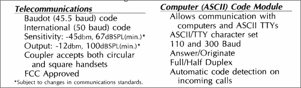
| BAUDOT | BAUDOT @ 45.45 baud | Annex A | |
| INTERNATIONAL | BAUDOT @ 50 baud | Annex A | Ultratec Supercom |
| CCITT | ITU V.21 | Annex F | means V.21 |
| ASCII | BELL103 | Annex D ? | seen in Ultratec phone manuals |
| EDTN | ITU V.21 @ 110 baud | Annex C | Ultratec Compact |
Sometimes the menu allows you to select the BAUD rate.
DUPLEX have a carrier that would annoy a Hearing person
SIMPLEX is harder to define.
Above the HALF-DUPLEX modes only transmit when needed, using the same MARK and SPACE frequencies for TX and RX.
MARK and SPACE come from Teegraphy. Some Telegraph machines put a mark on a paper tape and some decoded the character and printed it.
http://www.computer-timeline.com/timeline/emile-baudot/ mentions "The printing telegraph of British-American inventor David Edward Hughes"
I am not too sure what the definition of DUPLEX, HALF-DUPLEX, SIMPLEX
 DUPLEX - channels can be used at the same time.
 SIMPLEX - channel can ony be used in one direction - source to sink.
 HALF-DUPLEX - channels can be used one at a time.
If you pair multiple channels, each could be SIMPLEX, to allow DUPLEX communication.
For SPEAK, TYPE, HEAR, READ, we have a rich combination of DUPLEX , HALF-DUPLEX SIMPLEX.
We say TCP/IP which is TCP over IP. We can use similar notation to list our options.
So we could say ( as in TCP/IP or TCP over IP )
 VOICE / phone handset / PSTN
 VOICE / Headphone / PSTN
 VOICE / Earbuds / MOBILE
 VOICE / Hands free  / MOBILE
 TEXT / modem
 TEXT / IP
 TYPE / PC keyboard / PC
 TYPE / smartphone soft keyboard / Mobile
 TYPE / plug keyboard / Mobile
 TYPE / bluetooth keyboard / Mobile
 READ / laptop screen / PC
 READ / smartphone screen / smartphone
http://ccgi.dougrice.plus.com/cgi-bin/wiki.pl?My_Unknown_Theorem_Examples
If the channel supports DUPLEX the users may still need to use HALF-DUPLEX.
List the path end to end and write down when the path needs to go to HALF-DUPLEX.
The HALF-DUPLEX points are like the narrow bridge or speed chicane on roads.
The call has been set up and both ends can TALK or TYPE.
These are HALF-DUPLEX points.
Textphone, used keyboards and UARTS and modems to send the typing over the 2-wire Telephony using audio instead of voice:-

and Textphone, used modems UARTS and displays to display the typing over the 2-wire Telephony :-

Summary of a 2-wire Phone:-
- X - Switch controlled by microcontroller in phone.
 phone line -- [ Hookswitch ] - X - [ bell / alerter ]
                                X - Caller ID -- [ display ]
                                X - To Hybrid
 [ dtmf keypad ] - [ dtmf  IC  ] - X --|
 [ microphone  ] - [ audio     ] - X --|
 [ keyboard    ] - [ modem     ] - X --|
                                       |-- to Hybrid
 from Hybrid --|
               | -- [ audio         ] - X - [ loudspeaker / handset ]
               | -- [ modem         ] - X - [ display   ]
http://www.dougrice.plus.com/dougnapTheory/index.htm has notes about 2-wire phones and Hybrids
https://www.britishtelephones.com/diagrams/n846.pdf has the circuit for phone and explains the hookswitch.
The hook switch used to connect the Bell circuit across the line until the User picked up the handset.
The bell was AC coupled to the phone line. When the user picks up the handset, The phone draws current.
With the handset off hook the hybrid circuit was connected to the phone line.
The line current powered the phone and signalled that the phone was off hook.
Modems that plug into a phone line have a similar functional block diagram.
This link tried to document the names of the signals on the RS-232 cables. The names date back to the early 1960's when computers and modems were in seperate boxes.
http://ccgi.dougrice.plus.com/cgi-bin/wiki.pl?Modems
This link has some interesting early history, which explains the confusing names used for signals and abreviations.
https://www.auvik.com/franklyit/blog/history-of-the-modem/
Early modems for V.21 had a RS232 interface and loads of signals defines in the RS232 and V.24 specs. ITU V.25 and ITU V.8 describe calling and answering tones used to establish connections.
ITU V.25 is worth a read as it specifies how a modem sends calling tone and answer tone. Modems work over a variety of telephone circuits and private wires with many ways of signalling. A modem needs a simple calling and answering tone signalling.

More modern modems may have a USB plug and use the AT commands.

WebAPI? allows a webpage to be used to interface to the modems
http://ccgi.dougrice.plus.com/cgi-bin/wiki.pl?AT_Commands_-_Serial_Using_Web_Browser
UARTS need some STOP to get a reliable START. So expect some "1", STOP or MARK to flush out the UART. to send a character START is send followed by the data bits and at least one STOP bit.
If STOP is not seen a Frame error may be raised and lock out interrupts on some microcontrollers.
ITU V.18 states "Carrier is transmitted 150 ms before the first character is transmitted."
However my Ultratec Supercom and Compact do not send a front porch of MARK. (1400Hz), and start with space(1800Hz)
So for BAUDOT Silence could be mapped to MARK and "1".
Summary:-
 START - SPACE - "0" - RS232 or V.28 more than 3V  - Microcontroller TX low
 STOP  - MARK  - "1" - RS232 or V.28 less than -3V - Microcontroller TX High
Note: The MAX232 chips invert the voltages. Microcontrollers TX and RX are not.
Serial - Drawn using wavedrom:-

V.21 needs carrier to be sent for a period before the data.
When I used my V.18 web page to generate samples, I needed to add some front porch MARK before the data was decoded. See:- ITU V.21 circuit 109 table 2/V.21
The user should hold back sending data until carrier is received as it indicates an end to end connection. CD is on when Carrier is received. The Originate end waits for CD before sending Carrier.
My USB modem could be configured to disable the hangup on loss of carrier, and you could use the ATD and ATA commands to return to TEXT.
When I used ATD to return to TEXT, it did not send CARRIER so the line remained silent.
If I used ATA it sent carrier and the modem re-trained.
When you press a key on my Ultratec Supercom and Ultratec Compact, you do not hear them chirp if they not receiving carrier. The Supercom has a red LED, and the Compact reports "NO CCITT CARRIER".
If you set the Ultratec Compact to CCITT ANSWER is sends 1650Hz MARK carrier.
If you set the Ultratec Compact to CCITT ORIGINATE, it waits for 1650 Hz before sending 970Hz MARK.
ITU V.21 TABLE1/V.21 and RS-232 names:-
| Circuit | Designation | RS-232 |
| 105 | Request to Send - RTS | RTS |
| 106 | Ready For Sending - RFS | CTS |
| 109 | Data channel received line signal detetctor | CD |
| 125 | Calling indicator | RI |
ITU V.24 "List of definitions for interchange circuits between data terminal equipment (DTE) and data circuit-terminating equipment (DCE)"
The C in DCE is "Circuit-terminating" not "computer" - easy to be confused. -
https://www.analog.com/en/resources/technical-articles/fundamentals-of-rs232-serial-communications.html is well worth a read.
https://pinoutdiagrams.com/cable/rs232-null-modem-cable-pinout
When I had my first PC about the the time of the IBM XT PC, we used serial ports and RS232 leads. I did not have a dial-up modem. The RS232 leads could be tricky to get to work. I had a Ball Point Pen test, short pin 2 and pin 3 and see if you got an echo when using Putty or HyperTerm?.
At the time, I never really understood DTR , DSR, DTR, RTS, CTS in the modem context and without the modem, it is easy to get confused. DCE does not mean "Data Computer equipment", it is short for "data circuit-terminating equipment" (DCE).
 [ computer running Terminal software ]--[ RS232 lead ]---[ modem ]--[ Telephone line ]--[ modem ]--[ computer ]
                                                  DTE ->|-> DCE
We used:-
  [ computer running Terminal software ]--[ RS232 lead wired as null modem ]---[ computer ]
                                                                       DTE ->|-> DCE
People used to have a box to fake the signals to get RS-232 leads to work, and there are various null-modem wiring diagrams.
I suppose the computer program had to wait until these signals indicated the computer at the other end was connected.
[#RS-232]
RS232 is very much alive, but more at the API interface than the DB25 cable.
ITU V.24 defines the circuits. The diagrams below are useful summaries.
This document has a very useful summary.
See the Cable and Adapters diagrams. The Minimum Straigt Cable diagram explains how the signals are grouped.

Normal timing sequences during establishment of communications are shown below.
On half duplex circuits, RTS is dropped as soon as the data is sent. This is to signal a turn around of the circuit.

 DTR > _ _ - - - - - - - - - - - - - -
 DSR < _ _ _ - - - - - - - - - - - - -
 RTS > _ _ _ _ - - - - - - - - _ _ _ _
 CTS < _ _ _ _ _ - - - - - - - - _ _ _
  TD > _ _ _ _ _ _ - - - - _ _ _ _ _ _
CD < from modem indicating Carrier is being received.
So this should be used to hold back buffered user typing.
If characters are received before CD is asserted, It could be the V.18 CI.
Check if there is a frame error or parity error. Check if they are spaced correctly.
Microchip 16F877 stop bits can be used for 9th bit Address.
Some UARTS lock if there is an overrun error and need to be reset. e.g. Microchip 16F877
See the Cable and Adapters diagrams.
The API used still hang onto the RS232 signals.
Some API documents for windows and Linux.
Using Web_serial to do RS232 to a Modem.
https://developer.mozilla.org/en-US/docs/Web/API/Web_Serial_API
http://ccgi.dougrice.plus.com/cgi-bin/wiki.pl?AT_Commands_-_Serial_Using_Web_Browser
Typically the Modem takes a serial signal, using voltages encoding the "1"'s and "0" using MARK and SPACE and uses FSK frequency Shift keying.
[computer program]--[UART]--[modem]--[telephone system]--[modem]--[UART]--[computer c program]
The UART interface to the computer program is summarised as a TX and RX register and two flags TxEmpty? and RxFull?.
CPU - UART:-
  A write to TX resets TxEmpty?.
  A read from RX resets RxFull?.
UART - Host:-
  A read from TX sets TxEmpty?.
  A write to RX sets RxFull?.
If you have a FIFO then there need to be changes.
 TxEmpty? may need to be TxSpaceAvailable?
 RxFull? becomes RxAvailable?

I have a JavaScript? page that explores this: http://www.dougrice.plus.com/dev/DigiSpark/text0.html
Between the UART and the C program is a lot of API.
https://developer.mozilla.org/en-US/docs/Web/API/Web_Serial_API
http://www.dougrice.plus.com/dev/serial/rpi_ser_tcc.c
And these dabbles to try driving an old modem over a serial port. The Webpage does not always see the USB modems, so I have to use a serial lead plugged into a Modem.
Not all modems recognise the same AT commands and these do not work.
The web pages automate driving the modem just enough and can always be copied and extended.
https://homepages.plus.net/dougrice./dev/DigiSpark/simpleterm/simpletermModem.html
https://homepages.plus.net/dougrice./dev/DigiSpark/simpleterm/simpletermModemOne.html
V.21 modems are FULL DUPLEX and uses these frequencies
 ITU-T v.21
  Originate
    1080 = Carrier
    1180 = Space (Carrier + 100Hz)
    980 = Mark (Carrier - 100Hz)
  Answer
    1750 = Carrier
    1850 = Space (Carrier + 100Hz)
    1650 = Mark (Carrier - 100Hz)
By using four frequencies , it is possible to use the 2-wire Telephony. so both diagrams (a) and (c) can be used.
In the diagram (c) ( two wire - FULL DUPLEX ) , It would be more difficult to detect the CARRIER if the TX and RX used the same carrier.
In the diagram (a) ( four wire - FULL DUPLEX ) , consider only transmitting if the carrier from the other end is present.
BAUDOT only sends when a key is pressed and the modem listens and RX is disabled when it is sending.
This is 2 wire - Half Duplex
   BAUDOT: - 5 bit
 * carrier (for 150ms) + 0 + 11000 + 1 (for 40ms)
 *
 * 0 - 1800Hz - SPACE
 * 1 - 1400Hz - MARK
 * START 0
 * STOP  1
 *
It has an added complication of needing to shift between letters and numbers which must be tracked for both directions.
https://learn.adafruit.com/clue-teletype-transmitter/tty-fundamentals
There is a EDT mode that is also 2 wire - Half Duplex and uses the V.21 frequencies , but 110 BAUD.
In the diagram (b) ( two wire - HALF DUPLEX ) , consider only transmitting using BAUDOT or EDT based on the method used from the other end.
The CD output should ensure that the carrier has been present for long enough and at a strong enough level.

It is okay to transmit a "ping" test character sequence if the CD has not been detected a carrier from the other end.
See ITU V.8 for examples.


A TDM telephone system can be sumarised by this diagram, where the codecs are clocked at multiples of 8kHz sample rate. Jitter buffers were used as well.

The microphone voltage is sampled at 8000 times per seconds. TDM expects the clk to be sychronised to a common point.
You could do this:
If you have TX and RX, TDM got it right.
If the blocks are not clocked from a central source, you get slips. It is possible to slip less than a sample period if you use a DSP to upsample to a higher sample rate and down sample. This is a bit like converting to analogue and mixing and resampling.
Below is a reference telephone circuit from DL Richard's book "Telecommunications by Speech" from 1970's. A Phone line is two wires of equal length and equal impedance. The voltage across the phone is midway between the power supply voltage. There were different guages of coper wire used. BPO630 has a table.

https://dfrtelecoms.org.uk/dialtele.htm has a simple introduction to how a phone works.
https://www.robkalmeijer.nl/techniek/telecom/telefonie/index.html has some useful summaries and has this really simple diagram of a telephone.
http://www.dougrice.plus.com/dougnapTheory/index.htm and http://www.dougrice.plus.com/dougnapTheory/indexFurtherNotes.htm has some more theory about the two wire telephony. Rice simplified Webb's equations for a telephone exchange in PO630 , which is available from the BT Heritage site. PK Webb also wrote PO603. These were written in the 1970's and are about 50 years old.
https://www.digitalarchives.bt.com/Calmview/Record.aspx?src=CalmView.Catalog&id=BTA%2f3+BT1%2f11+RES%2fRES10%2f15%2f630&pos=7 PO630 Computation of the Characteristics of Telephone Connections
and
https://www.digitalarchives.bt.com/Calmview/Record.aspx?src=CalmView.Catalog&id=BTA%2f3+BT1%2f11+RES%2fRES10%2f15%2f603 PO603 - The Definition and Measurement of the Characteristics of Telephone Sets
Computation of the Characteristics of Telephone Connections
So it is possible to write down a list of 2x2 matrices and for each frequency use a computer to work out the the Microphone to earphone sensitivities. In about 1984, I was using a NASCOM 2 , Z80 based computer using BLS pascal. At some stage I purchased Turbo Pascal 3.0 for CP/M on an Amstrad 664, and also for the IBM PC. In 2009, the code was converted to JavaScript? to run on the web browser.
The model for the four wire exchange model becomes:

and matrices for each element:

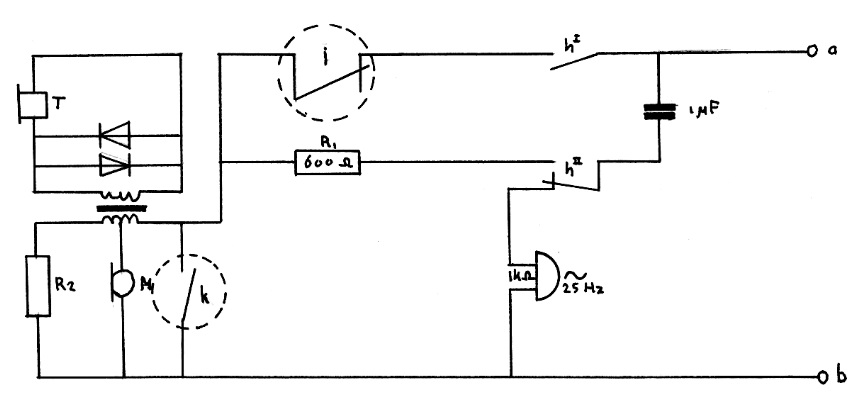
Hybrid using a transformer, similar to that used in GPO dialphone:-

This simplified circuit from a real phone schematic. It drives the line using a voltage controlled current source, and is line powered.
( The Bell and Hookswitch have been omitted to keep things simple. )
https://www.phonepages.org.uk/portfolio-item/statesman/

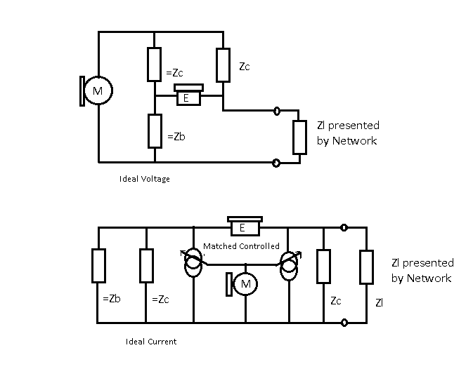
Using Thevenin / Norton Theory to redraw the equivalent circuit:-
http://www.dougrice.plus.com/dougnapTheory/indexFurtherNotes.htm
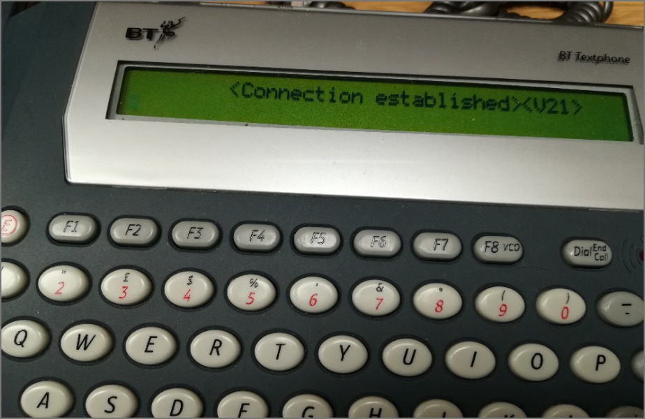
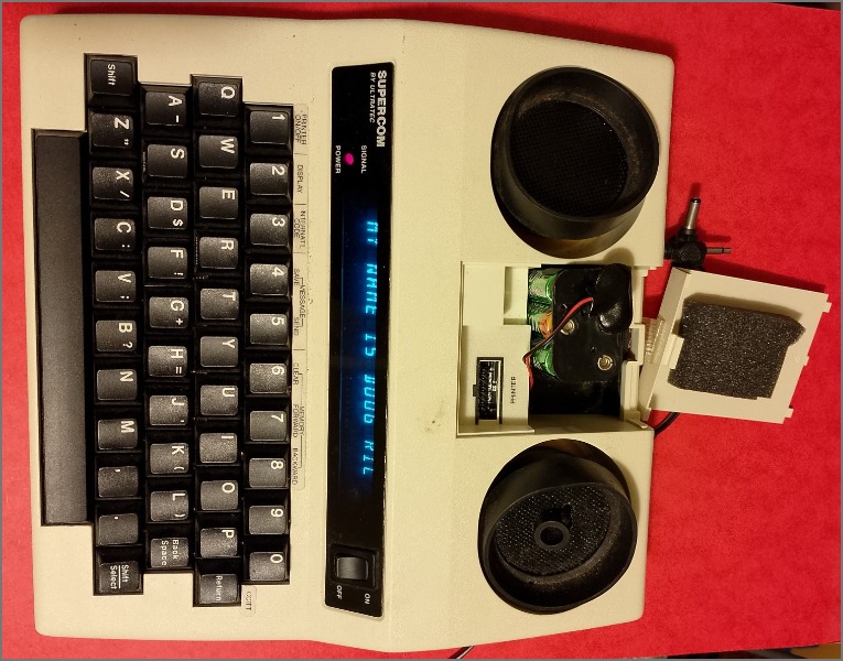
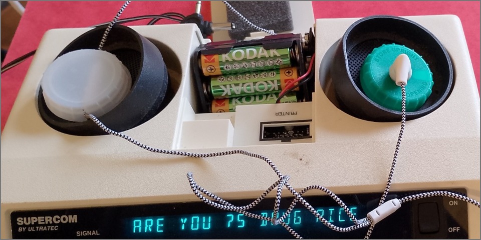
This BT Textphone has trained up V.21 and can be used.
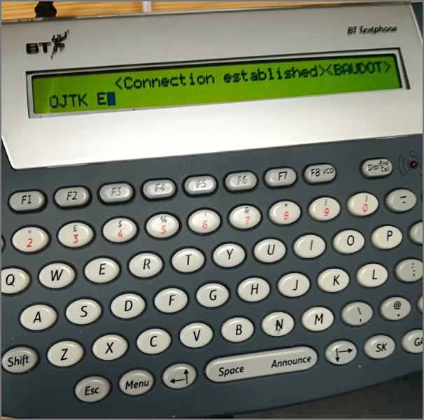
Here it has trained up using BAUDOT
It factory resets to ITU V.18 Annex G which sends CI as specified in ITU V.8 and V.18 and waits for ANS 2100Hz
Read ITU V.25 for the Modem setup sequence. Short burst are sent so that the V.21 Carrier Detect is not turned on.
However it can be configured to each of the ITU V.18 Annex
It can be used to do VCO with a second phone and the VCO button or Shift-VCO
This is an early version of the Ultratec Supercom.
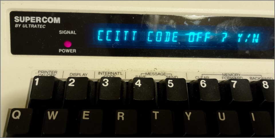
This defaults to BAUDOT when you turn it on.
It seems to support the same codes listed in the Ultratec Superprint 200 manual
The later versions that have the SK and GA keys use a different set of modulations.
It uses the acoustic coupler. You dial on a PSTN landline and place the hanset on the acoustic coupler. Later versions have a telephone lead as well.
To AutoDetect?, you may need to dial the call on the PSTN phone, and place the handset on the Ultratec textphone and turn it on.
If the Ultratec Minicom is unplugged, it whistles ITU V.21 mark 1650Hz just after turn on.
The Ultratec Compact has a blue adendum leaflet. It sends 1650Hz on the first key press after turn on.
You use the signal indicator to tell if you have voice or modem at the other end.
Ultratec manuals include this:
I tried to use earbuds and microphone and milk bottle tops.
Here I use the earbuds mounted in washing up foam pads to make a proof of concept acoustic coupler.
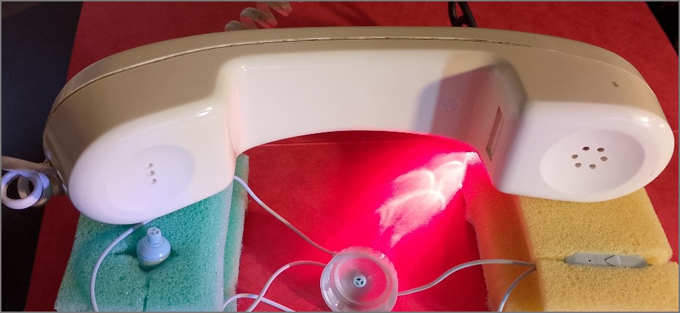
Webaudio is used to send and receive BAUDOT squarks.
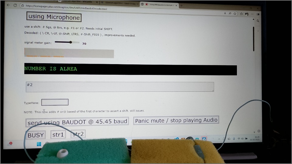
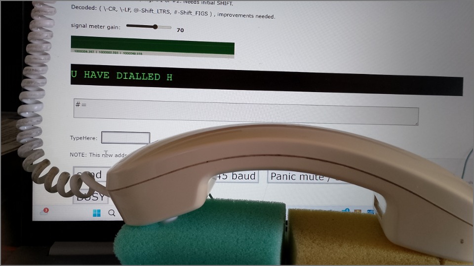
The landline PSTN phone is used to dial, and the Webpage, webaudio and "proof of concept" Acoustic coupler used to send and receive BAUDOT.
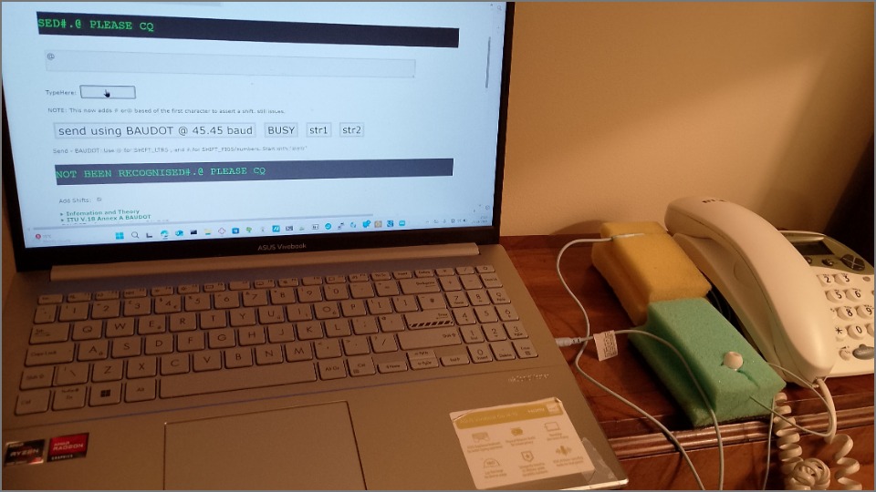
https://homepages.plus.net/dougrice./dev/UART/micBaudotDecode.html - proof of concept webpage
simplified Hybrid used in Post office 706 and 746 from the 1960's
Consider the coil, assume the windings are the same, so the voltage across each winding are the same.
If ZL == the Balance Z components, and the Earphone is high impedance, then when the voltage V3+V2 == V1+V across Zl, the Voltage across The ear phone will be minimal when the person speaks.
When the person does not speak, the AC Voltage across the MIC will be zero so V Earphone will be -V across ZL.

Circuit for Post Office 706 Telephone

Loop Dis dialling for Post Office 706 Telephone

Telephones use DTMF to speed up the signalling.
http://ccgi.dougrice.plus.com/cgi-bin/wiki.pl?DTMF_Dabbles
Once established , a phone call is between KNOWN and KNOWN end points and allow either end to talk next.
The Client Server model, only allows the Client talk to the Server, which can respond. A PEER to PEER protocol needs to be engineered on top, with keep alives
Client Server is from an UNKNOWN to a KNOWN, but
IP4 addresses makes the endpoints UNKNOWN


There are only four things certain in life
 1) Taxes
 2) Death
 3) Our company's Early release Schemes
 and
 4) Re-Engineering IP protocols to have a keep alive!
The Web Browser is a useful tool!
![[Home]](../ipstats.gif)